Building a USB-C Guitar Hero controller
May 20, 2023
I love USB-C. I love rhythm games. I also love building random things that I don’t particularly need. This build fulfils all three of those things for me. And it’s finally done.
This won’t really be a guide, more just me talking about my little journey of building my own Guitar Hero controller, though I hope it does prove to be helpful or cool to at least one person.
CONTEXT
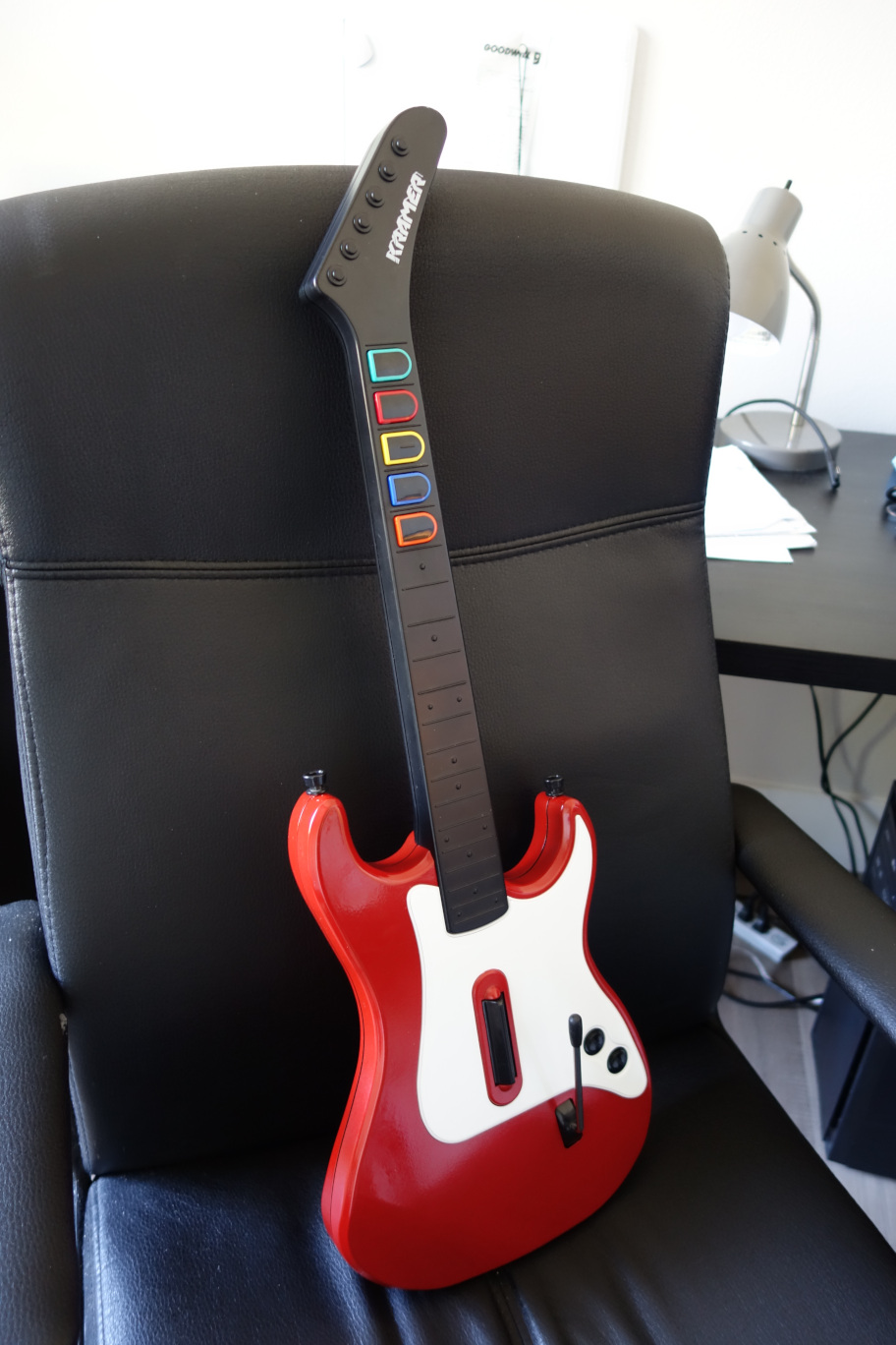
Almost a month ago now, I went thrifting and I found a Guitar Hero guitar, specifically a PS2 Wireless Kramer controller, for about 7 dollars. (check my post talking about this :D)
It looks much more different than it does now!
I’ve always had an interest in playing Guitar Hero and Clone Hero, but I didn’t want to deal with all the ordeal with buying a specific controller and using adapters and whatever. Many guitars are discouraged from being used for Clone Hero or for use on PC due to many incompatibilies, issues with the actual controller design, etc. So instead of dealing with that, I thought it would be fun to repurpose this now useless and very much NOT sought after Guitar Hero controller and bring new life to it by giving it a complete makeover, both cosmetically and internally.
CLEANING THE GUITAR
I sadly don’t have many pictures of this process, so I’ll try to describe it the best I can.
It sucked.
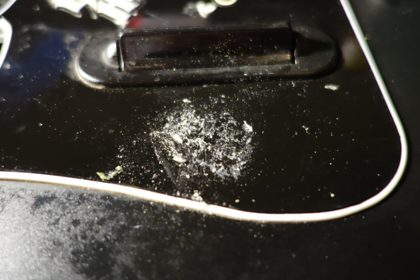
Some stubborn and gross sticker residue
There were a ton of stickers on the guitar, probably over a decade old by now, so removing them was a pain, each sticker had to be scrapped off and drowned in Goo-Gone. The big stickers were especially horrible. After a while of going and coming back to give my hands a break, I got all the stickers off the guitar.
From there, I just gave it a quick wipe-down and also gave some parts a little Magic Eraser and sanding in order to prepare it for painting. Speaking of which…
PAINTING THE GUITAR
I already made a post about this, so I won’t go to much into it, but to give a quick run-down, I painted the main part of the guitar red, which I already discussed in this post. After that post though, I got some white spray paint and also painted the center glossy part. From there, I painted both parts with several coats of extremely glossy clear coat.
I think it honestly turned out pretty alright, considering I’ve barely ever used spray paint prior to this, and I’m really glad that the gloss turned out pretty neat looking.
MODDING THE INTERNALS
(NOTE: I did a terrible job taking pictures and journaling this, so I apologize for the lack of pictures for a while.)
Before talking about the process of modding, here’s my list of tools and parts I used for reference:
TOOLS
- Soldering iron
- Torx 10 and Philips head screwdriver
- Tweezers
- Desoldering pump/braid
- Craft knife
MATERIALS
- Raspberry Pi Pico
- Jumper wires
- Hot glue (lots of it)
- Panel mount Micro USB to USB-C adapter
- Solder and flux
ORDERING THE PARTS
After I finished painting, I went on Adafruit and ordered several parts, here’s my little list :)
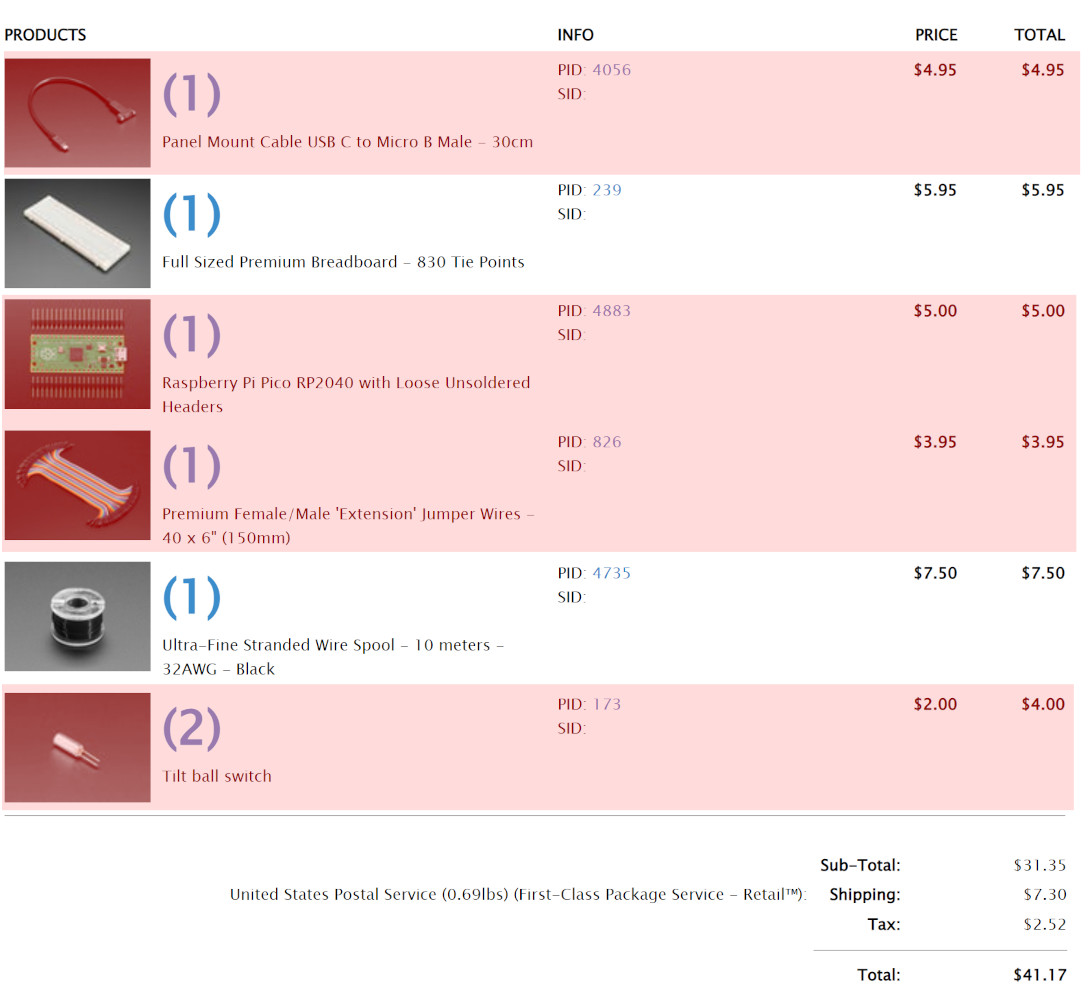
(the ones highlighted in red are the ones used for this project, the other parts are for something else)
I hope you know what Adafruit is, but if you don’t, they’re an amazing website for buying electronics parts. If you ever need parts for a project, this site is what I recommend.
Overall, without the other stuff on that list, the parts for this project cost about 30 dollars. The brain of the controller will be the Raspberry Pi Pico, which we will use to program as a controller for use on PC with a tool I’ll talk about a little later. The Micro-B to USB-C is used to adapt the Pico’s Micro USB port to a much more… not terrible port, while also giving more cable length for me to fit things nicely inside the case. The wires are for… well, wiring. And I ordered two tilt-ball switches for using Star Power on the controller, which is activated by tilting the neck up. I ordered 2 switches because according to some people online, it should help provide a more accurate input without misreads… or something like that.
After a few days, I got the parts in the mail and it was now time to mod the parts.
REMOVING THE OLD PARTS
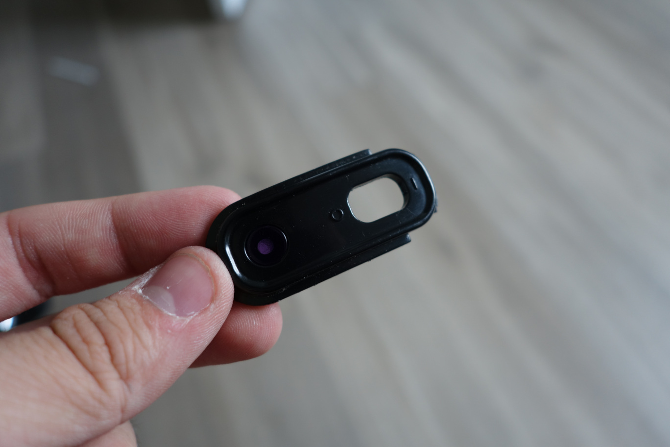
I already had the guitar open since it was painted and I reinstalled the old parts inside, but I took out the power switch and LED, along with the battery compartment, since we wouldn’t need those anymore. It was a matter of just unscrewing them and pulling them out, so very straightforward.
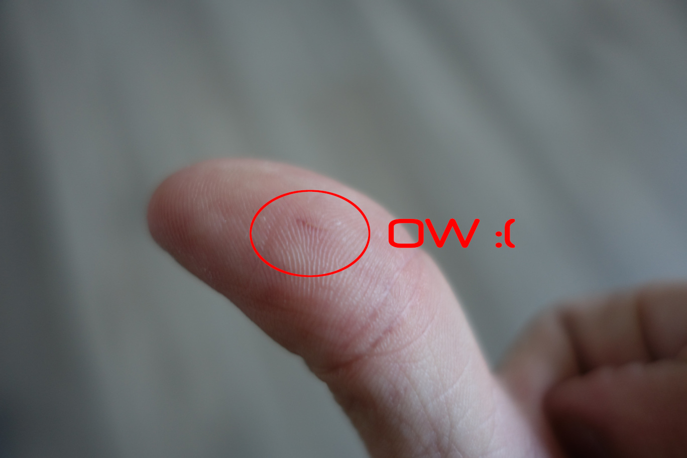
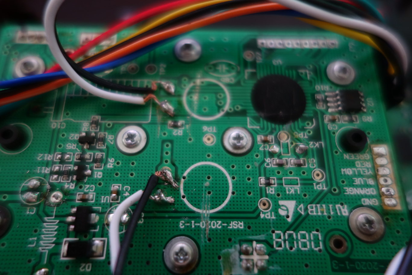
I also went out of my way to remove the old wireless antenna, some of the big capacitors on the board, and other random small parts that weren’t needed anymore, mainly just capacitors and wireless stuff. I did cut my thumb on a capacitor leg though, so that wasn’t fun.
Be safe when working with electronics!
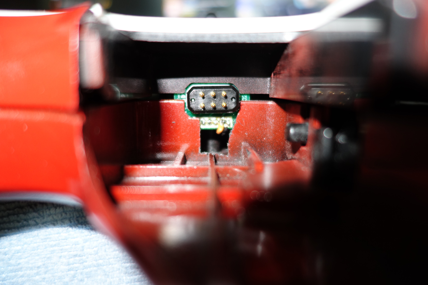
THE NECK CONNECTOR
After that, I had to desolder this little daughterboard, which had the pins that connect to the neck of the guitar, from the mainboard, and I wired several jumper wires that corresponded to the colored buttons and the pinout, which was conveniently labeled on the mainboard.
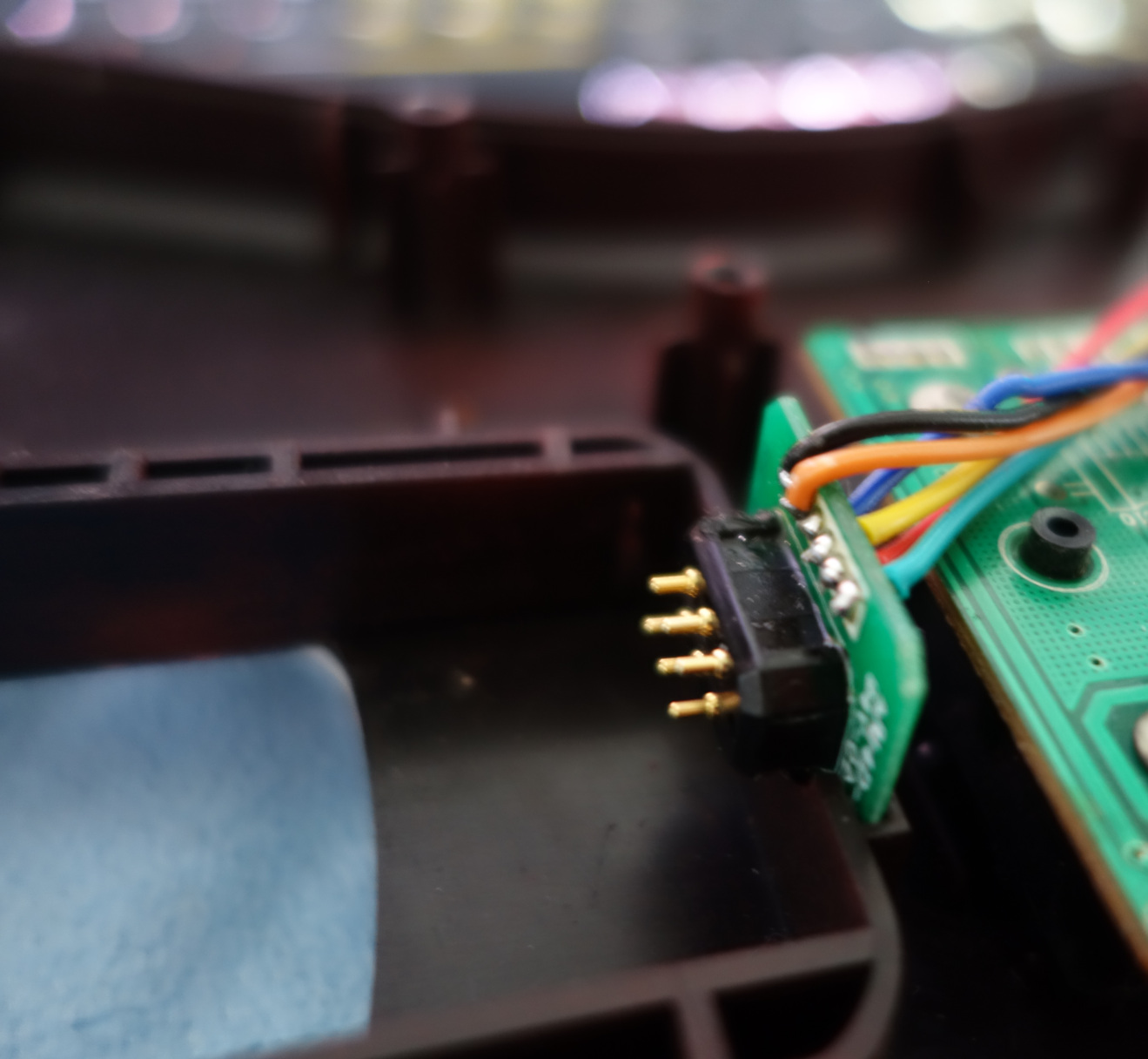
I wasn’t able to clear the holes for the orange pin and ground, so I had to surface-mount them, and because of that, the wires interfered when closing the case. Because of that, I had to cut this hole in the case in order for the wires to fit and the case to properly close.
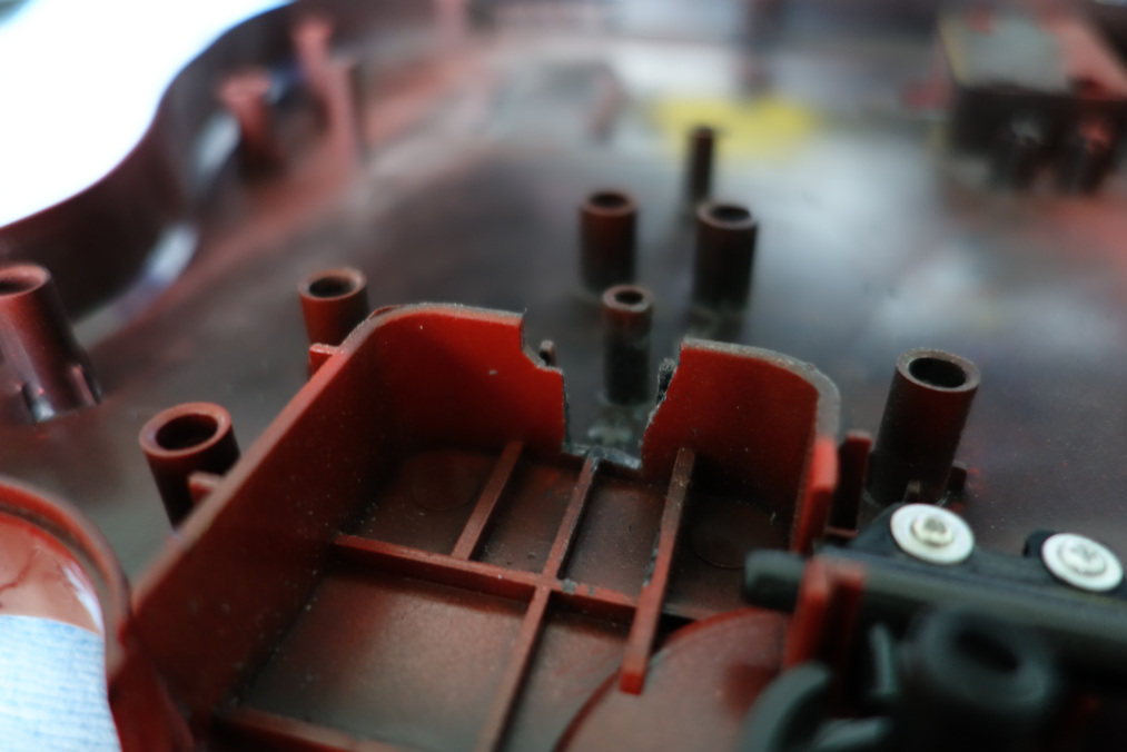
I may have cut the hole a little too big. Oops!
I wasn’t really happy to have to do this, but now the case closes properly and, to be fair, the neck will be plugged into the guitar anyways, so you won’t even see this hole. I may cover it up with tape or something in the future, but it doesn’t bother me too much anymore.
WIRING THE STRUM BAR
Wiring the strum bar was fine, it’s basically just two buttons, so I wired two wires on each button.
I also cut the traces around it with a craft knife since apparently, not doing this can cause phantom inputs (basically just random inputs you didn’t make) because of the circuitry around the buttons being active when using them.
WIRING THE WHAMMY BAR
The whammy bar uses three pins, and I had the exact colors of wire they used, so doing that was really straightforward, I just desoldered the old wires and replaced them with jumper wires.
WIRING START AND SELECT
Start and Select are on a seperate board which uses three wires, so I simply desoldered the old wires and resoldered new ones. For some reason, I was having issues getting the wires in and being too thin since they wouldn’t properly fit through the holes, but I got it figured out.
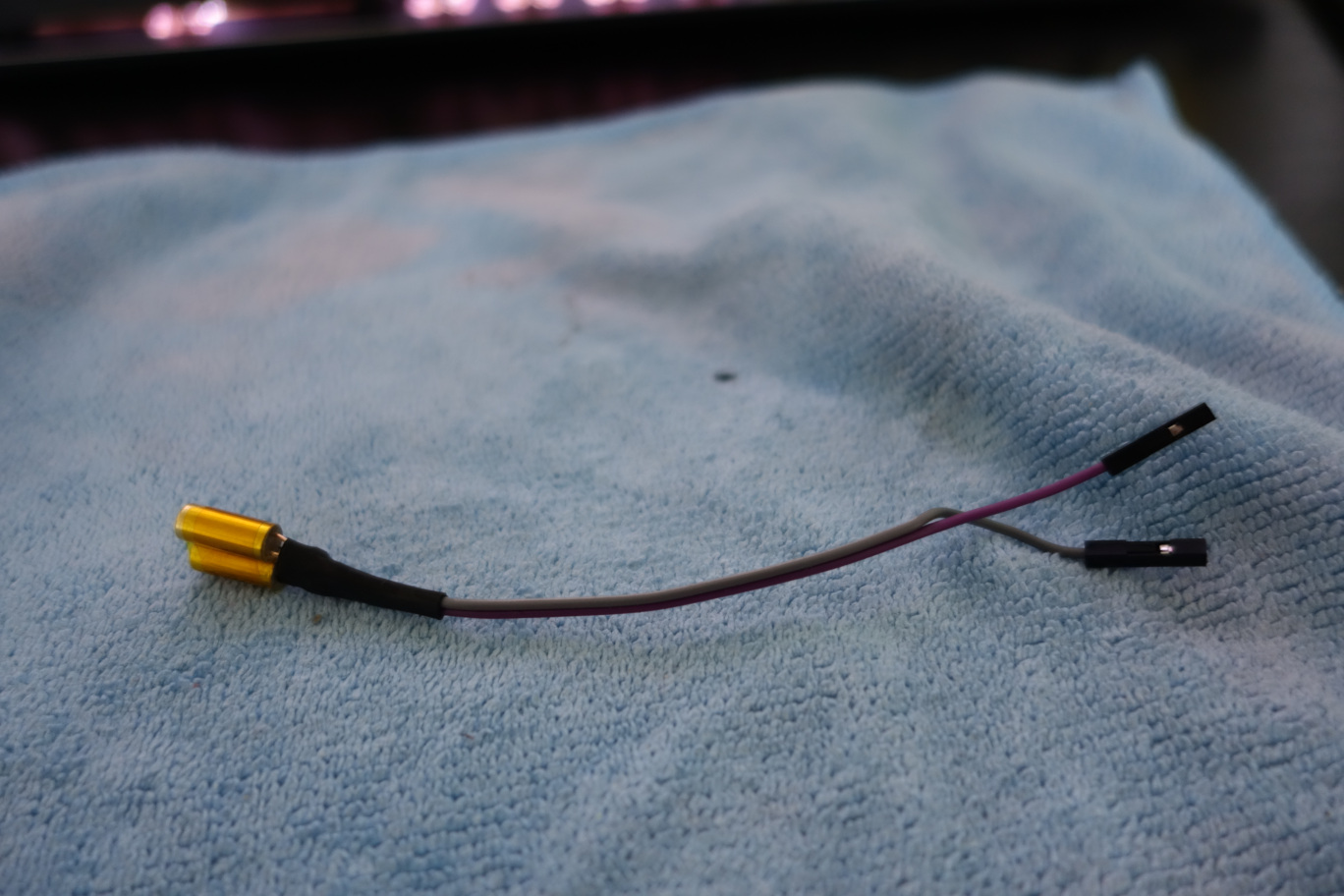
WIRING THE TILT INPUT
The board inside the guitar actually already has a tilt sensor on it, but I ordered other tilt sensors because I don’t know, why not? In retrospect, I probably could’ve just stuck with using the board’s tilt sensor, but it’s fine, I didn’t think about that when ordering my parts.
I wired both tilt sensors in series so that the tilt can only activate when both sensors are active, if only one is active, the signal won’t pass through.
I just wired them, used some heat shrink to cover the pins, and then wrapped the sensors in Kapton tape to keep them together.
Looks pretty good, huh?
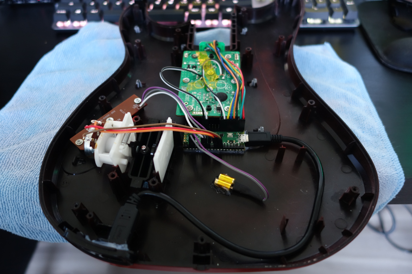
MOUNTING THE PI PICO
After I finished soldering new wires to everything, I needed to mount the new parts, starting with the Pi Pico. I decided to mount it directly below the mainboard, since it looked tidy and was the best place where all the wires could reach it without too much strain. To mount it in the case, I used a lot of hot glue, which I know isn’t the best, but it should work perfectly fine, since this won’t have much strain put on it.
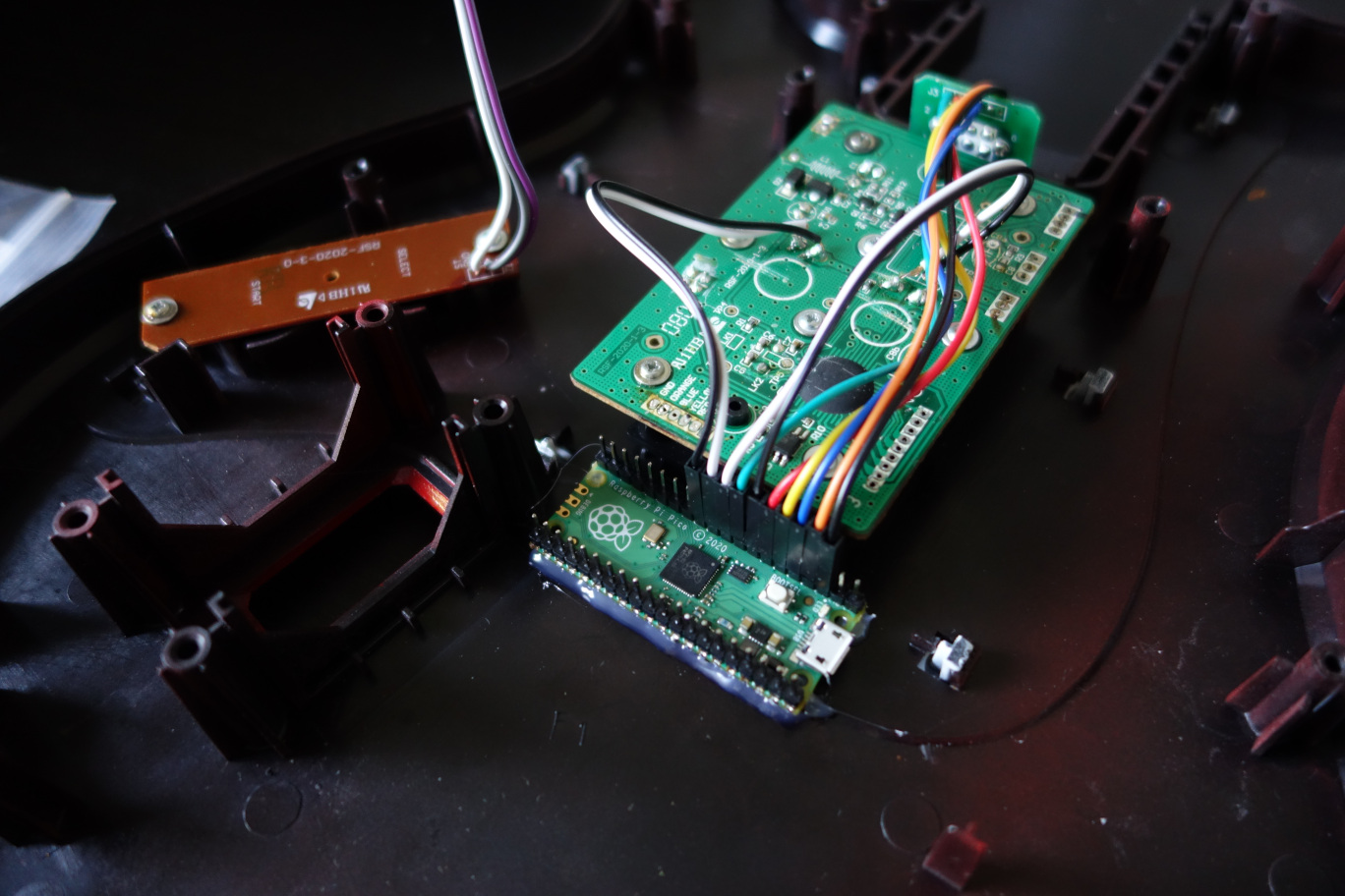
I also got a little head-start with plugging things into the Pico haha
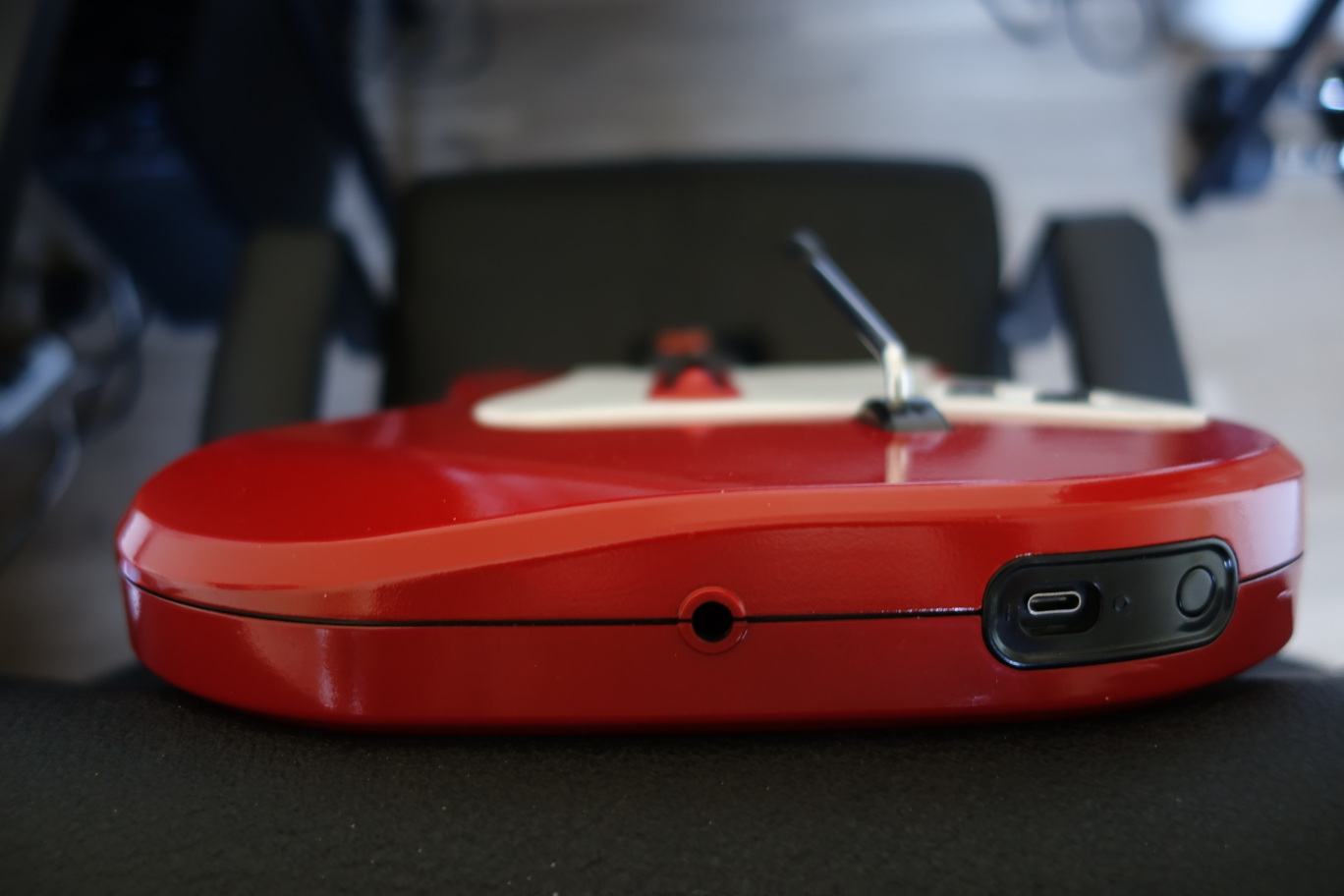
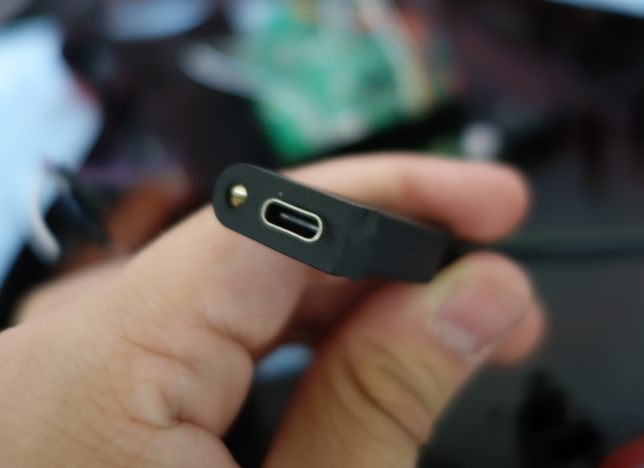
MOUNTING THE USB-C PORT
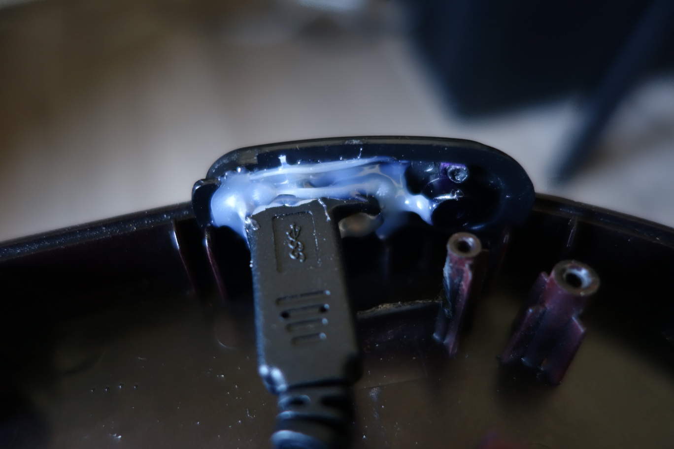
On the bottom of the guitar, there’s this little black piece that holds the power switch and LED. This proved to be a perfect place to put the USB-C port at, since the hole was big enough to fit a port and the cable going in it, and the plastic around the USB-C port was big enough to cover the hole.
To mount it, I took out the screws it came with and cut one of the screw holes out to make it fit on the plastic cover.
From there, I aligned the port and then used a ton of hot glue to mount it on the plastic piece. I hope the hot glue lasts a while… I also had to cut out some plastic from one of the mounting posts on the whammy, since it was interfering with the wire. Even with it cut though, it barely fits, but fits enough that it should be fine.
I think the port turned out looking really good though, almost like it’s official. Very proud of that. And plugging cables in and out feels good too, it’s not too hard to, so I’m not terribly worried about applying too much force on it.
PLUGGING EVERYTHING INTO THE PICO
I now needed to wire everything to the Pico. This was pretty straightforward, since I just needed to wire all the buttons to any ground and digital pins, which the Pico has plenty of, and then the whammy needed to be wired to some analog ports, and I needed to plug the USB-C cable to the Micro USB port. I also had to mount the tilt, which was the same as wiring the other buttons, but I also needed to hot glue it to the case, which wasn’t hard at all. And that was all for wiring.
PROGRAMMING THE PICO
To program the Pico, I used the Ardwiino Guitar Configurator, a very useful program that programs your Pico for you and provides a very convenient way to map your buttons. While the name suggests it’s meant to be used for Wii guitars, it can actually be used to configure any guitar that you can get the Pico inside of. I’m not gonna go into depth with it, since doing this was pretty much just a matter of plugging it in and pressing buttons and stuff, so I’ll close this section off by saying thank you very much to sanjay900 for creating the Guitar Configurator, the link to the Github page and guide is here!
PLAYING THE GAME
I suck at it, but it’s fun.
CONCLUSION
This project was really fun honestly, I learned a lot, and now I can finally play my favorite guitar game…
HHAHAHA I LIED TO YOU ALL IM NOT PLAYING GUITAR HERO IM PLAYING GUITAR FREAKS BITCHHHHH HAHAHAHHAHAHHAHHA